Tools & Service Equipments
Tools & Service Equipments
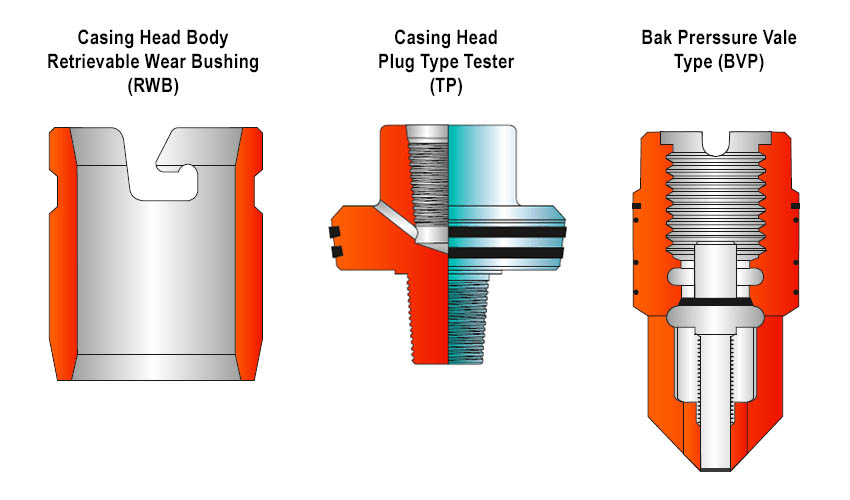
Casing Head Body Retrievable Wear Bushing (RWB)
These retrievable wear bushings (RWB) protect the inner containers of casing head bodies or spools during drilling operations. When wear bushings are used, either hold down screws in the top flange of the casing head body or hold down flanges with hold down screws are required.
Retrieving Tool (RT)
This tool (RT) is meant for retrieving the wear bushing described above. It is inserted in the slot provided in the wear bushing top surface, rotated and then pulled up with the tools.
BOP Test Plug (TP)
These plug Testers fit all nominal sizes of casing head bodies and tubing heads and are available with any standard tool joint.The test plugs are assembled in the drill string and lowered to its seat in the casing head body or tubing head. Pipe rams of the preventors are then closed and hydraulic test pressure is applied below the rams.Blind rams can be tested in the same manner after removing the drill string.
Back Pressure Valve (BPV)
Tubing hanger bushing are furnished with female lift and suspension threads and are machined to accommodate the type (BPV) back pressure valve as shown in the figure. With Blowout Preventor equipment attached to the tubing head body, the tubing is run to the desired depth and the bushing, with the type (BPV) back pressure valve installed, is made-up on the landing joint. The wrap around hanger is then latched around the tubing below the hanger bushing and lowered thru the BOP to its position in the tubing head body by means of a landing joint. After making sure that the hanger have fully landed in the head, hold down screws are fully tightened to compress the packing and secure it in place. Thereafter the landing joint & BOP may be removed. Attach the landing joint and raise the tubing enough to install a spider and slips. With tubing weight on the slips, remove landing joint.

The Hanger Spool with X-Mas Tree Manifold attached is then lowered and sealed on the hanger bushing. The union nut may now be made up by hand and a spanner wrench. The tree cannot now be rotated.Raise the tree assembly enough to remove the spider and slips. At this point, the well can be displaced and the packer set under complete pressure control.Final nipple up operations are then completed and the type PBPV back pressure valve is removed from the hanger bushing with a lubricator.
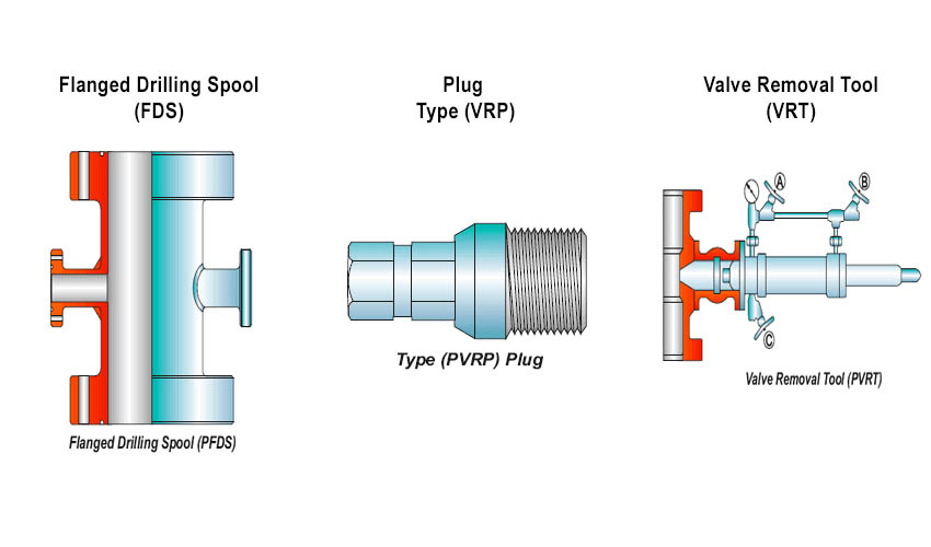
Flanged Drilling Spool (FDS)
These are designed to allow unrestricted circulation of mud in the well and provide flexibility in arranging flow line openings in blowout preventor hookups. Studded or open faced ends and outlet connections can be provided. Generally hub of the flanged outlet is welded. Height of spool will vary form 24″ -36″. However spools as per specific need of customers can also be provided.
Valve Removal Plugs (VRP)
All flanged or studded outlets on PARVEEN’s casing heads, casing spools and tubing heads are threaded for valve removal plugs. All plugs have standard API Line Pipe Threads and are small enough to pass thru the valve to be removed. The plug is installed when the valve is to be removed and removed when the valve is to be installed.
Valve Removal Tool (VRT)
These are generally pressure-balanced manual hydraulic tool designed for safe and reliable operations in the installation and removal of valve removal plugs, in order to install or replace a well-head outlet valve under pressure conditions.This tool is also designed to accommodate 2 1/16”, 2 9/16”, 3 1/8” Valve upto 10000 PSI WP. Adapter may be provided for use with 1 13/16”, 2 1/16”, 2 9/16”, 3 1/8” flanged valves and screwed end valves. Various sizes of valve removal plug sockets are also provided for the respective sizes of plugs.In the figure above, Needle Valve ‘A’ is located next to pressure gauge on manifold by-pass assembly and needle valve ‘B’ is connected to 1/2″ NPT TEE on far end of manifold bypass assembly. Needle Valve ‘C’ is a bleeder valve located behind flange packing.

| Specification of THSCL & THDCL Type Tubing Hanger | |||||
| Nominal Flange Size | Tubing Hanger Type | Casing Pipe | |||
| 2 3/8 Up TBG | 2 7/8 Up TBG | 3 1/2 Up TBG | 4 1/2 Up TBG | ||
| 7 1/16 | THSCL | X | X | X | |
| THSDL | X | X | |||
| 9 | THSCL | X | X | X | X |
| THSDL | X | X | X | X | |
| 11 | THSCL | X | X | X | X |
| THSDL | X | X | X | X | |
Note : All Dimensions are in Inches.
